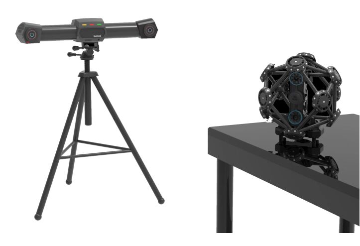
TrackScan Pro Laser Ottico Scansione Fotografica Portatile Sistema di Scansione di Tracciamento Dinamico
I. Parametri tecnici del prodotto
1.1 Tracciante
Modalità di localizzazione: localizzazione fotografica a infrarossi in tempo reale
* Metodo di connessione: il tracker dispone di un processore ad alte prestazioni integrato, collegato al computer tramite cavo attraverso il controller hub.
Modalità di splicing: splicing di trasferimento basato sul punto di marcatura di riferimento (non è necessario incollare il punto di marcatura nella modalità di misurazione a stazione singola)
* Volume di misura: 16,6 m3
Dimensioni di misura: (3000 X 2500 mm) @ 3000 mm, fino a 4000 X 3000 mm
Distanza di lavoro: 2 m ~ 4 m
Velocità di misura: 60 fps
* Precisione del volume: 0,06 mm @ 9 m 3, 0,075 mm @ 16,6 m 3
Accuratezza estesa: 0,044 mm + 0,015 mm/m con sistema fotogrammetrico CoordMeasis
1.2 Scanner
Modalità di scansione: scansione fotografica laser manuale
* Tecnologia di scansione: tecnologia di scansione a griglia di linee laser (41 linee laser blu, 26 linee laser trasversali standard + 14 linee laser transversali fini + 1 linea laser blu)
* Tecnologia di trasmissione: modalità cablata e modalità wireless, il modulo wireless supporta la sincronizzazione wireless del dispositivo e la trasmissione wireless dei dati
* Area di scansione: fino a 600 mm × 550 mm
Distanza di riferimento: 300 mm
Profondità di campo: 400 mm
* Velocità di scansione: 2,100,000 misurazioni/secondo
Risoluzione di scansione: 0,02 mm
Accuratezza di misura: 0,025 mm
Categoria laser: 2m (sicuro per gli occhi)
1.3 Penna leggera
* Metodo di misura: misurazione a contatto
* Modalità di connessione: identificazione ottica automatica, senza necessità di acquisizione del pulsante
Ripetibilità: 0,03 mm
Velocità di misura: 50 FPS o superiore
1.4 Sistema completo della macchina (sistema di scansione di tracciamento)
modalità di misura: non è necessario incollare punti di marcatura nella modalità di misurazione di tracciamento e nella modalità di misurazione di una sola stazione,e solo un numero molto ridotto di punti di marcatura deve essere incollato in modalità di misurazione di trasferimento.
Modalità di connessione: collegare tutti i dispositivi componenti nel loro insieme tramite un controller hub (supporto per impostare lo scanner come modalità di connessione wireless)
Modalità di splicing: basata sul punto di riferimento obiettivo, supportando la misurazione in una singola stazione e la misurazione in una stazione di trasferimento
Distanza di misura: fino a 16,6 m3 in modalità di misurazione a stazione singola e praticamente illimitata in modalità di misurazione a stazione di trasferimento
Accuratezza del volume: 0.06mm@9.1m 3, 0.075mm@16.6m 3
Accuratezza estesa: 0,044 mm + 0,015 mm/m con sistema fotogrammetrico CoordMeasis
II. Funzione del sistema
* 2.1 Il sistema è composto da un tracker, uno scanner, una penna luminosa, un controller, un software di misura e un software di rilevamento.La scansione e la misurazione possono essere scambiate liberamente. I dati di scansione e misurazione possono essere unificati automaticamente nello stesso sistema di coordinate.
2.2 Tutte le attrezzature e i cavi del sistema devono essere collocati e trasportati in scatole di imballaggio per l'aviazione, sicure, affidabili, portatili e facili da trasportare.
2.3 Il sistema può funzionare normalmente in condizioni di lavoro di temperatura da 0 °C a 40 °C, umidità < 90%, varie luci interne o ambiente esterno non luminoso.Adotta la tecnologia di scansione laser (sicurezza oculare), e può scansionare direttamente l'oggetto misurato con effetto riflessione diffusa sulla superficie senza pre-spruzzo di trattamento bianco di sviluppatore.riflettenti e molti altri materiali.
2.4 Il sistema supporta due modalità di connessione cablata e di connessione wireless, vale a dire che tutti i dispositivi hardware possono essere collegati al computer tramite un controller;o lo scanner può essere scollegato dal controller e passato allo stato di connessione wirelessEntrambe le modalità di connessione hanno una capacità di trasmissione dei dati altamente stabile.
2.5Il sistema supporta la scansione combinata di montaggio o smontaggio.Dopo che le parti sono smontate e scansionate, tutti i dati di scansione possono essere unificati automaticamente nel sistema globale di coordinate.
2.6 Il sistema dispone di una tecnologia integrata di compensazione anti-scosse,che possono realizzare misure normali in condizioni di lavoro particolari quali vibrazioni del pezzo di lavoro misurato o installazione instabile dell'apparecchiatura, sia che si utilizzi uno scanner o una penna luminosa.
2.7 Il sistema ha la funzione di alternare liberamente tra la scansione di tracciamento e la scansione autonoma. Per pezzi più grandi, è possibile selezionare la funzione di scansione di tracciamento.Per pezzi di piccole dimensioni o non adatti alla scansione a tracciamento, la modalità di scansione autonoma può essere attivata per la scansione.
2.8La penna luminosa del sistema adotta una tecnologia di identificazione ottica automatica, che può essere utilizzata per la misurazione di caratteristiche di riferimento, di caratteristiche invisibili e di caratteristiche facilmente occluse.Il sistema avvia in modo intelligente il comando di campionamento senza premere il grilletto durante la misurazione, evitando così l'impatto delle vibrazioni del grilletto sulla precisione di misurazione durante il campionamento.
2.9 La risoluzione di scansione del sistema può essere regolata liberamente e l'utente può scegliere la risoluzione di scansione in base alle dimensioni del pezzo da lavorare o ai requisiti di misura.
2.10 Il sistema è in grado di produrre formati di dati generali quali nuvola di punti o griglia e il formato di output è compatibile con molti software CAD comuni.
III. Funzioni del software
3.1 Il software ha una serie di funzioni quali nuovo progetto, salvataggio del progetto e progetto aperto, e supporta la scansione 3D, il monitoraggio 3D, la misurazione della penna luminosa, la misurazione del fotogramma e altre modalità.
3.2 Il software ha le funzioni di regolare la distanza tra i punti di scansione, regolare i parametri di scansione, cambiare automaticamente l'angolo di visione della scansione, indicare lo stato del suono e della luce,e renderizzare il modello tridimensionale;
3.3. Il software integrerà automaticamente ogni dato di scansione nel sistema globale di coordinate e fornirà funzioni di modifica come selezione / selezione inversa, cancellazione / rimozione,Display/hide per nuvola di punti 3D.
3.4Una volta completata la scansione, i dati della nube di punti tridimensionale possono generare una superficie a maglia triangolare STL.e la nube di punti ottenuta può essere rapidamente incapsulata in una maglia triangolare di alta qualitàIl processo di malleazione comprende una lavorazione speciale come la rimozione di chiodi, l'eliminazione di piccoli componenti e le caratteristiche di affilatura.comprese le operazioni generali quali il riempimento di fori di magliaLa funzione di riempimento di buchi a maglia ha molteplici opzioni, come il riempimento di buchi normali e il riempimento di buchi a punti segnati.
3.5Il software può unire automaticamente due o più file di progetto scansionati e allineare i dati scansionati sotto diversi sistemi di coordinate allo stesso sistema di coordinate attraverso punti di marcatura comuni.
3.6 Il software ha funzioni di taratura della fotocamera, taratura della penna, taratura del robot e altre funzioni di taratura:
(1) Calibrazione della telecamera: quando il localizzatore è trasportato o sottoposto a forti urti meccanici, i parametri delle due telecamere all'interno del localizzatore possono cambiare.l'utente può ricalibrare il tracker attraverso la funzione di calibrazione della fotocamera;
* (2) Calibrazione a penna leggera: quando l'utente smonta e sostituisce la punta di sfera di rubino e la punta di acciaio al carbonio,l'utente deve ricalibrare la punta della penna luminosa attraverso la funzione di calibrazione della penna luminosa;
(3) Calibrazione del robot: se il localizzatore è installato alla fine del robot o se il localizzatore è installato fisso rispetto alla base del robot, the user can use the robot calibration function to calibrate the coordinate conversion relationship between the coordinate system of the tracker and the coordinate system of the end of the robot or the coordinate system of the robot base.
3.7 Il software dispone di funzioni di misurazione geometrica del telaio, quali telaio di ripresa, telaio di ottimizzazione e telaio di tracciamento:
(1) Fotografia del quadro: dopo che l'utente ha incollato i punti segnati sul pezzo rigido,le coordinate tridimensionali di questi punti contrassegnati possono essere misurate attraverso la funzione di riprese di fotogrammi ed esportate come file fotogrammi;
(2) ottimizzazione dell'inquadratura: per le coordinate tridimensionali dei punti segnalati ottenute con la ripresa dell'inquadratura,la precisione del fotogramma può essere ulteriormente migliorata sulla base dell'algoritmo di ottimizzazione globale multi-vista attraverso la funzione di ottimizzazione del fotogramma;
* (3) Quadro di tracciamento: l'utente può importare in anticipo i file di quadri di più pezzi rigidi (non più di 20).e quindi misurare il valore 6-Dof di ogni pezzo in tempo reale attraverso la funzione di tracciamento quadro quando questi pezzi rigidi si muovono liberamente nello spazio.
3.8 Il software ha le funzioni di misurazione a penna di luce, misurazione di particelle, misurazione di distanza, misurazione delle caratteristiche, gestione delle caratteristiche, ecc.:
(1) Misurazione della penna luminosa: può misurare le coordinate tridimensionali della punta della penna luminosa o il valore 6-Dof del corpo della penna luminosa.Fornisce due modalità di misurazione singola e di misurazione continua. In modalità di misurazione singola, non è necessario alcun intervento dell'utente.In modalità di misurazione continua, si può ottenere la traiettoria di movimento della punta della penna.
(2) il software identifica automaticamente lo stato della penna luminosa in base all'immagine e attiva l'azione di misura senza Bluetooth o trasmissione di rete o interruttore chiave;evitando così l'influenza della vibrazione della chiave sulla precisione di misurazione durante l'acquisizione dei punti;
(3) Misurazione delle particelle: questa funzione può essere utilizzata per scattare le coordinate tridimensionali di tutti i punti segnalati nel campo visivo del tracker.si può ottenere la curva "tempo di spostamento" dei punti contrassegnati;
(4) Misurazione della distanza: cliccare con il mouse su un qualsiasi punto della visualizzazione 3D per misurare rapidamente la distanza tra i due punti;
(5) misurazione delle caratteristiche: quando un utente importa caratteristiche geometriche di base quali un punto, una linea retta, un piano, una circonferenza, una sfera, un cilindro, un cono e simili,la distanza o l'angolo tra due elementi può essere misurato in tempo reale quando le entità corrispondenti si muovono liberamente nello spazio;
(6) Gestione delle caratteristiche: gli utenti possono importare file di nube di punti ottenuti con la ripresa di fotogrammi o la misurazione con penna leggera, adattare caratteristiche geometriche di base come punti, linee rette, piani, circonferenze,sfere, cilindri, coni, e misurare le distanze o gli angoli tra queste caratteristiche, e creare sistemi di coordinate degli utenti basati su queste caratteristiche.Il sistema di coordinate del file di nuvole di punti è stabilito sul pezzo di lavoro stesso in base ai requisiti di progettazione del pezzo di lavoro.
3.9 Modulo di elaborazione a maglia triangolare
- Dopo la scansione, la nube di punti ottenuta può essere rapidamente incapsulata in una maglia triangolare di alta qualità, e il processo di maglia include un trattamento speciale come la rimozione di picchi,eliminazione di piccoli componenti, e caratteristiche di affilatura;
- Sono fornite ricche funzioni di elaborazione della maglia, comprese le operazioni generali come il riempimento dei fori della maglia, l'allineamento della maglia e la riduzione della maglia,tra le quali la funzione di riempimento di fori a maglia ha molteplici opzioni come il riempimento di fori normali e il riempimento di fori a punti segnati.
3.10 Input e output dei dati
- I risultati esportati sono in formato file ASC e STL point cloud, e le interfacce di output dei dati sono estese.Imageware e altri software 3D.
IV. Elenco delle attrezzature
| Numero di serie |
Nome |
Specifica/modello |
Quantità |
| 1 |
Tracker |
Unità di visione industriale ad alta precisione |
Guarda la videocamera |
2 serie |
| Fonte luminosa a infrarossi e circuito di controllo |
Vedi Traccia-Infrarosso |
1 pezzo |
| Processore integrato ad alte prestazioni |
SeeTrack-Computer |
1 set |
| 2 |
Scanner |
Unità di visione industriale ad alta precisione |
RayScan-Camera |
2 serie |
| Fonte luminosa laser e circuito di controllo |
RayScan-LaserVX5 |
1 pezzo |
| Unità di raccolta senza fili (accessorio opzionale) |
RayScan-WirelessBox |
1 set |
| 3 |
Penna leggera |
Con punta di rubino e corpo di alta resistenza |
Vedi Tracking-Probe |
1 pezzo |
| 4 |
Controller |
Fonte di segnale sincrona di alta precisione integrata, modulo di alimentazione, modulo di calcolo, modulo hub e altri componenti |
SeeTrack-Controller |
1 set |
| 5 |
Software di sistema |
SeeTrack V6 |
1 set |
| 6 |
Sistema di taratura |
Vedi Track-Cali |
1 set |
| 7 |
Linea di trasmissione dati, linea di controllo, linea di alimentazione |
|
1 set |
| 8 |
Ricordate il punto |
6 mm |
5000 |
| 9 |
Istruzioni |
|
1 set |


 Il tuo messaggio deve contenere da 20 a 3000 caratteri!
 Italian


